Our Technologies

Side-channel blowers & compressors

Side-Channel Blowers & Compressors: Technical Working Principle, Components, and Industrial Uses

Side-channel blowers—also known as regenerative blowers or ring compressors—are widely used machines in industrial applications where a clean, oil-free, and reliable source of vacuum or compressed air is required. Their design allows for medium vacuum and pressure generation with high flow rates and minimal maintenance. Unlike positive displacement pumps, side-channel blowers rely on regenerative aerodynamics to build pressure or vacuum, making them unique in principle and performance.

At the heart of the blower is an impeller with multiple radial blades rotating inside a precisely engineered housing.

  • Air Inlet Stage
    • When the impeller rotates, atmospheric air (or process gas) is drawn into the inlet port.
    • The blades accelerate the incoming air radially outward due to centrifugal force.
  • Regenerative Energy Transfer
    • Instead of being discharged immediately, the accelerated air is trapped between the blade tips and the side channel.
    • The air circulates helically along the channel, re-entering the impeller at a slightly advanced position after every pass.
    • With each pass, kinetic energy imparted by the impeller is converted into pressure energy through the regenerative effect.
  • Discharge Stage
    • After multiple circulations, the air reaches the outlet port with significantly higher pressure (compression mode) or significantly reduced pressure (vacuum mode).
    • This process ensures a pulsation-free flow compared to piston or rotary vane technologies.
  • Centrifugal Force: Drives the air outward from the impeller blades into the channel.
  • Regenerative Effect: Repeated circulation allows incremental energy transfer, amplifying pressure without mechanical compression.
  • Pressure Differential: The blower creates a continuous difference between suction and discharge sides, enabling either vacuum generation or compression.
    11

Impeller

  • Multi-bladed, high-strength rotor (commonly cast aluminum alloy).
  • Directly mounted on the motor shaft for balanced, vibration-free operation.

Side Channel Housing

  • A spiral-shaped chamber precisely matched to impeller geometry.
  • The depth and width of the channel are critical design factors influencing pressure rise and flow rate.

Inlet & Outlet Ports

  • Positioned tangentially to maximize the efficiency of air intake and discharge.
  • Often fitted with silencers to reduce noise and pressure pulsations.

Electric Motor

  • Typically asynchronous (induction) motors operating at 2-pole speeds (~2,900–3,500 rpm depending on region).
  • Designed for direct drive, eliminating gear systems and reducing maintenance.

Bearings & Seals

  • High-precision ball bearings for long service life under continuous duty.
  • Gas-tight seals when handling corrosive or hazardous gases.

Cooling System

  • Most models rely on air cooling through an integrated fan.
  • For high-demand or ATEX-rated units, additional cooling jackets or external fans are used.
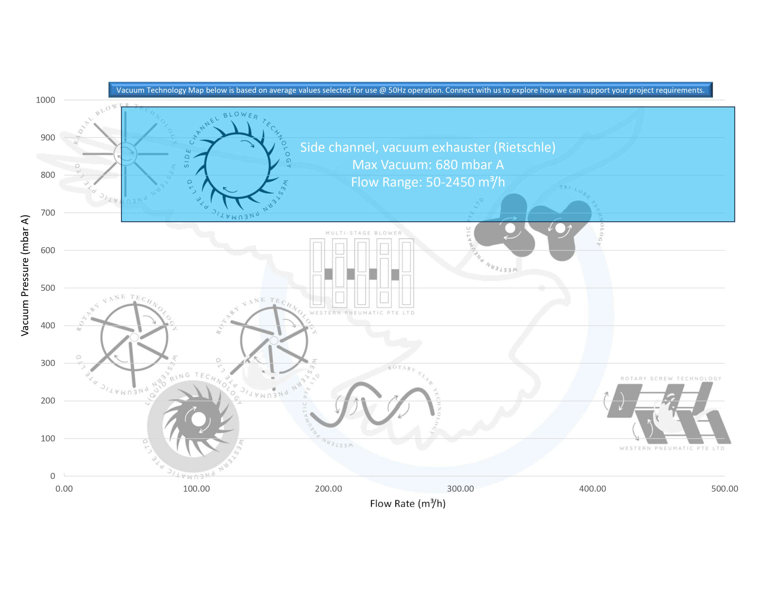
  • Vacuum Range: –300 mbar to –500 mbar (single-stage), up to –700 mbar (two-stage designs).
  • Pressure Range: +700 mbar to +1,000 mbar (single-stage), up to +1,400 mbar (multi-stage).
  • Not Suitable for High Vacuum: Cannot achieve deep vacuum (< –900 mbarA) like rotary vane or liquid ring pumps.
  • Medium Pressure Only: Limited compared to screw compressors or piston compressors.
  • Heat Management Required: Continuous operation at high compression ratios requires adequate cooling.